The drive end bearing is sealed on both sides and requires no added lubrication. The bearing inner race is a slip fit over the shaft. A drive end frame assembly is shown in Figure 9. Torque the shaft nut to 54-108 N M (4680 lb.-ft.). The slip ring end bearing assembly is covered in the next section.
-
Discard bearing retainer ring, Figure 4.
-
Install new ring.
-
To install new bearing. push on outer race until bearing bottoms in end frame. This procedure is not yet completed, see Step 12 after alternator is completely assembled.
-
Position regulator. rectifier bridge, and brush holder on work bench flat surface, solder or crimp connectors as in original assembly. Hold brushes in holder with pin.
-
To dissipate heat and make electrical contact place Copper heat Transfer grease, part no.698-T on end under rectifier bridge.
-
Position assembly in slip ring end frame, assemble fasteners.
-
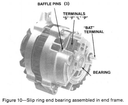
Assemble baffle, use punch to drive pins down flush with baffle.
-
Seat stator securely against end frame, solder three stator leads to rectifier bridge terminals.
-
Install cover, use punch to drive pins flush with cover.
-
Push on both inner and outer race of slip ring end bearing to assemble end frames together.
-
Assemble thru bolts. Remove brush holder pin.
-
With alternator assembled, push on both inner and outer race so slip ring end bearing seats
-
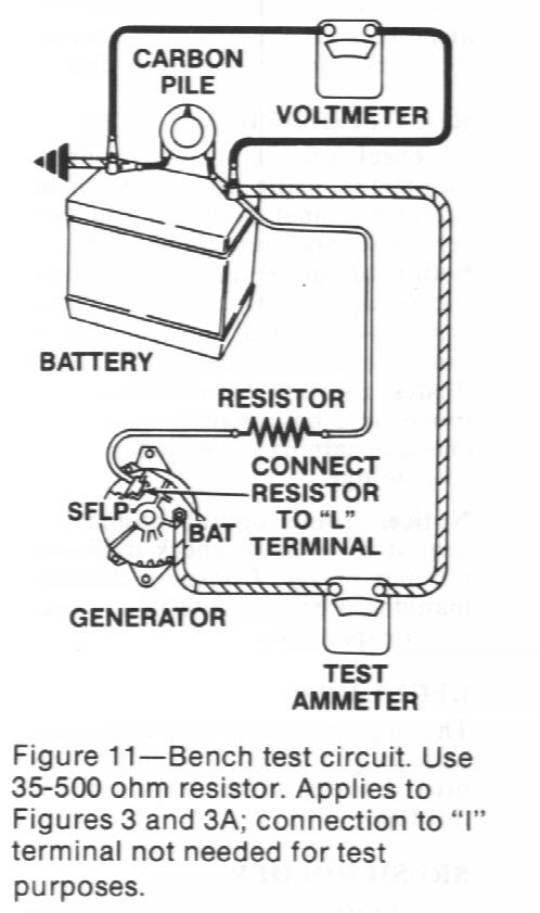
Make connections as shown in Figure 11, except leave the carbon pile disconnected. The ground polarity of alternator and battery must be the same. The battery must be fully charged. Use a resistor of any value between 35 ohm, 5 watt, and 500 ohm, 1/2 watt between battery and "L" terminal. This procedure applies to both circuits, Figures 3 and 3A.
-
Slowly increase alternator speed and observe voltage.
-
If the voltage is uncontrolled and increases above 16 volts, the rotor field is shorted or grounded, or the regulator is defective, or both. A defective rotor field coil can cause regulator defect. NOTICE: The battery must be fully charged when making this test.
-
If voltage is below 16.0 volts, increase speed and adjust carbon pile to obtain maximum amperes output. Maintain voltage above 13.0 volts.
-
If output is within 15 amperes of rated output, alternator is good.
-
If output is not within 15 amperes of rated output, the alternator is defective and requires repair.